
Shear walls and deep beams of a building model are available as independent objects in the design add-ons. This allows for faster filtering of the objects in results, as well as better documentation in the printout report.

When designing connections, you can now also insert a new member as a component directly in the Steel Joints add-on. This will only be considered for the connection design. You can use the Weld and Fasteners components to connect to other members.
Furthermore, it is possible to use the Member Section and Member Editor components and arrange reinforcement elements on the inserted member, such as stiffeners and tapers.
Go to Explanatory Video
Can you use some support? The "surface model" member type helps you to simulate a member as a surface model in the overall model.
This feature provides you with the following:
- Quick input using a member with a cross-section
- Simulation of openings in the web
- Simultaneous output of the member and surface results
- Design of member results in the add-on
- Consideration of a real stress distribution
You can use the surface member for the following applications, among others:
- Castellated beams
- Perforated beams
- Beams with rectangular openings
- Vierendeel trusses
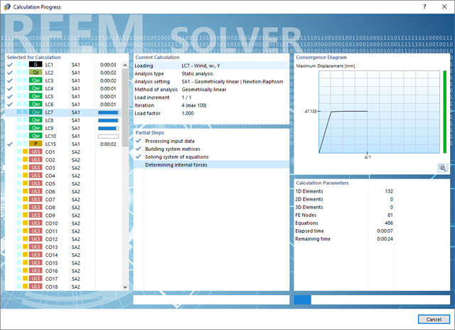
Do you have to calculate multiple load combinations in your models? Then several solvers (one per core) are initiated in parallel, each of which calculates a load combination. This ensures a better utilization of the cores and thus faster calculations.
Go to Explanatory Video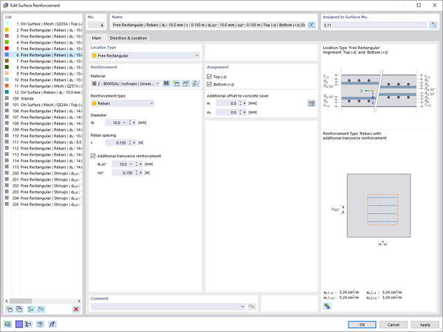
Dlubal Software makes many of your work steps easier to support you. Thus, the surfaces, members, member sets, materials, surface thicknesses, and sections defined in RFEM/RSTAB are preset to facilitate the data input. You can use the [Select] function at many places of the program to select the elements graphically. Furthermore, you have an access to the global material and cross-section libraries.
You can group surfaces or members into "Configurations", each with different design parameters. This way, it is possible for you to efficiently calculate design alternatives with different boundary conditions or modified cross-sections, for example. You will be amazed how much faster everything works with RFEM/RSTAB.
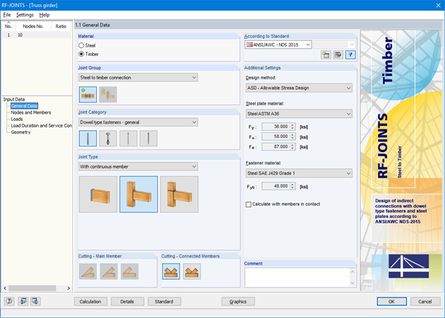
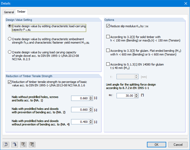
First, it is necessary to select the joint type, design standard, and steel plate and dowel material. For design according to EN 1995-1-1, you can select the SFS intec dowel system WS‑T. In this case, the corresponding material is preset in accordance with the technical approval of the manufacturer.
The connected members are imported from the RFEM/RSTAB model. The add-on module automatically checks if all geometry conditions are fulfilled. Alternatively, you can define the connection manually.
- The loading is also imported from RFEM/RSTAB or, in the case of manual joint definition, loads are entered. The Geometry window includes steel plate dimensions and fastener layouts.
Various languages are available for the results included in a printout report: English, German, French, Spanish, Italian, Czech, Slovak, Hungarian, Polish, Dutch, Portuguese, Russian, and Chinese.
You can create further language versions individually.
It is possible to import additional texts as RTF files. Page numbering can be configured as well in order to use prefixes, for example. Furthermore, you can export the printout report as an RTF or PDF file as well as in VCmaster.
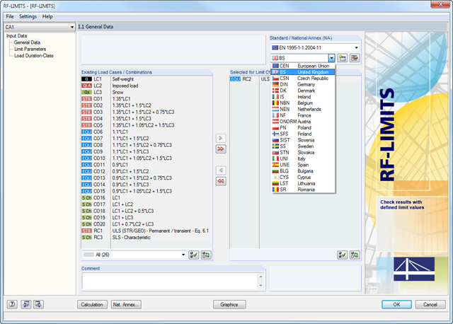
After selecting the loads required for the design and, if necessary, the desired standard for the design, you can define the limit loads in Window 1.2 Limit Parameters. In addition to the manufacturers listed in the limit library, it is possible to add user-defined entries.
After selecting all limit elements for the design, you can optionally define the load duration class (LDC). However, this module window is available only for timber fastener design according to EN 1995-1-1 or DIN 1052.
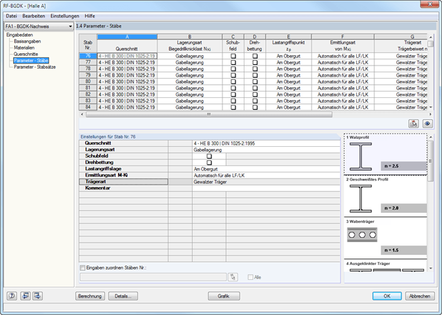
The details for the lateral-torsional buckling analysis are defined separately for members and sets of members. The following parameters can be set:
Support Type/Lateral-Torsional Buckling Load
- Available options are Lateral and torsional restraint, Lateral and torsional restraint or Cantilever
- Special supports are possible by specifying the degree of restraint βz and the degree of warping restraint β0. In this section as well, you can consider the elastic warping restraint of an end plate, a channel section, an angle, a column connection, and a beam cantilever by specifying the geometry dimensions.
- As an alternative, it is also possible to enter the lateral-torsional buckling load NKi or the effective length sKi directly
Shear panel
- A shear panel can be defined from a trapezoidal sheeting, bracing, or a combination of these
- Alternatively, you can enter the shear panel stiffness Sprov directly
Rotational restraint
- Choose between continuous and discontinuous rotational restraint
Position of Positive Transverse Load Application
- The z-coordinate of the load application point can be freely selected in a detailed cross-section graphic. (upper chord, lower chord, centroid)
- Alternatively, you can specify the data by selecting them or entering the data manually.
Beam Type
- For standard sections, the rolled beam, welded beam, castellated beam, notched beam, or tapered beam (web or flange welded) options are available
- For special cross-sections, it is possible to directly enter the beam factor n, the reduced beam factor n, or the reduction factor κM
After the calculation, the RF‑/JOINTS Timber - Steel to Timber add‑on module lists joint stiffnesses of all individual members, among other things. The following design results are displayed:
- Check of minimum spacing
- Load-carrying capacity of single fastener
- Steel plates (bearing resistance and stress according to EC 3 and AISC)
- Stress analysis with reduced timber cross‑section
- Block shear failure
- Total load carrying-capacity (including stiffness determination, transversal tension design according to EC 5, and others)
- Fire resistance design according to EN 1995‑1‑2
- Design of hinged, bending resistant, and semi-rigid connections
- Definition of up to 5 steel plates slotted in timber beams
- Up to 8 members connected to one node
- Thickness of steel plate 5 mm – 40 mm
- All sizes of fasteners
- Automatic check of the minimum distance between fasteners
- Optional free definition of fastener distances
- Definition of asymmetrical fastener arrangements (for example, any polygonal chains)
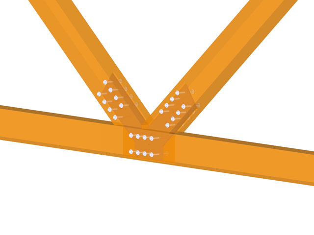
- Graphical visualization of joints in the add-on module and in RFEM/RSTAB
- All required steel and timber designs, including reduction of cross‑section values
- Design of transversal tension reinforcement (for EN 1995‑1‑1 only)
- Export of the member eccentricities to RFEM/RSTAB to be considered in the determination of internal forces
- Dowel length optionally shorter than cross-section width (for wooden plugs)
- DXF Export of Connection Geometry
- Fire resistance design according to EN 1995‑1‑2
Various languages are available for the results included in a printout report: English, German, French, Spanish, Italian, Czech, Slovak, Hungarian, Polish, Dutch, Portuguese, Russian, and Chinese. You can create further language versions individually.
It is possible to import additional texts as RTF files. Page numbering can be configured as well in order to use prefixes, for example. Furthermore, you can export the printout report as an RTF or PDF file as well as in VCmaster.
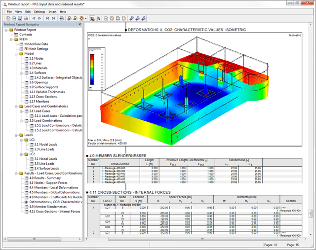
After the calculation, the results of performed designs, including all required intermediate values, are displayed in clearly arranged result tables sorted by various criteria. Since the program displays the intermediate values in detail, the transparency of all designs is ensured. It is possible to display the distribution of internal forces for each x-location of the beam in a separate graphical window. Here, both the deformations and the individual internal forces can be displayed.
Limit state designs are represented on members and the relevant fastener. This way, it is possible to retrace each value determined for calculation. Designs with design details and selected result diagrams can be added in the printout report, providing clearly arranged documentation. The printout report can include graphics, descriptions, drawings, and more. Moreover, it is possible to select which calculation data will be covered in the printout.
There are various options available for beam modeling. A roof type determines the exact purlin location for wind and snow generation.
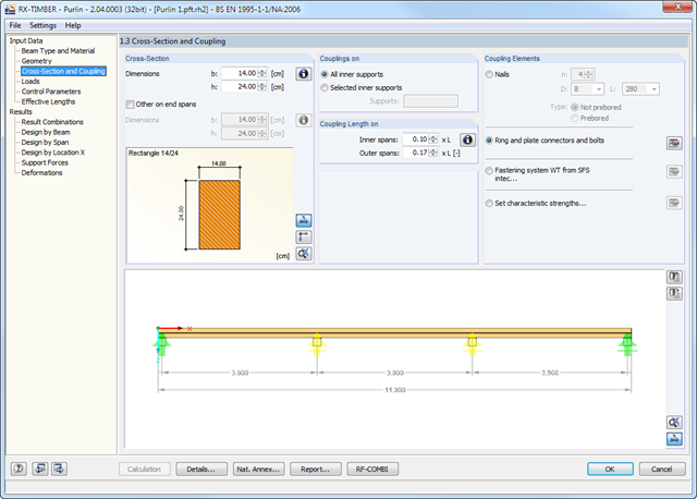
Two beam types are available: continuous beam and purlin. If you select the continuous beam, it is possible to define several hinge conditions of the beam. If you select the purlin, it is not possible to modify hinge conditions. In this case, the calculation considers a double cross-section in the coupling zone. In addition, several coupling elements are available in the purlin settings:
- Nails (prebored/not prebored)
- Ring and plate connectors and bolts
- Screw connection with fastening system WT from SFS intec
- User-defined specification using characteristic strength
The relevant timber grade of the material can be selected from the material library. All material grades for glulam, hardwood and softwood timber specified in EC 5 are available. Furthermore, you have the option to generate a strength class with user-defined material properties and thus extend the library.A comprehensive and extensible material library can also be used for entering permanent loads (for example, roof structure).
Generators integrated in RX-TIMBER Purlin allow for convenient generation of various wind and snow load cases. By clicking the information buttons, the map of wind and snow zones for the relevant country is displayed. The corresponding zone can be selected with a double-click. Load cases can be checked graphically.
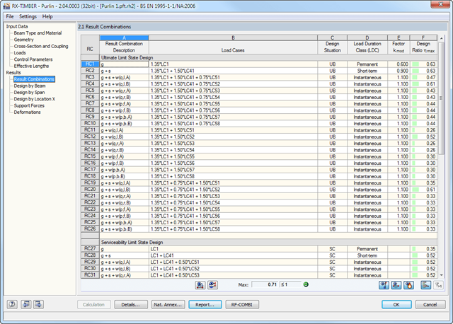
However, you can enter load specifications manually as well. According to the generated loads, the program automatically creates combinations for the ultimate and serviceability limit states as well as for fire resistance design in the background.
- Design of member ends, members, nodal supports, nodes, and surfaces
- Consideration of specified design areas
- Check of cross-section dimensions
- Design according to EN 1995-1-1 (European Timber Standard) with the respective National Annexes + DIN 1052 + DSTV DIN EN 1993-1-8 + ANSI / AWC - NDS 2015 (US Standard)
- Design of various materials, such as steel, concrete, and others
- No necessary linking to specific standards
- Extensible library including timber fasteners (SIHGA, Sherpa, WÜRTH, Simpson StrongTie, KNAPP, PITZL) and steel fasteners (standardized connections in steel building design according to EC 3, M-connect, PFEIFER, TG-Technik)
- Ultimate load capacities of timber beams by the companies STEICO and Metsä Wood available in the library
- Connection to MS Excel
- Optimization of connecting elements (the most utilized element is calculated)